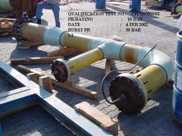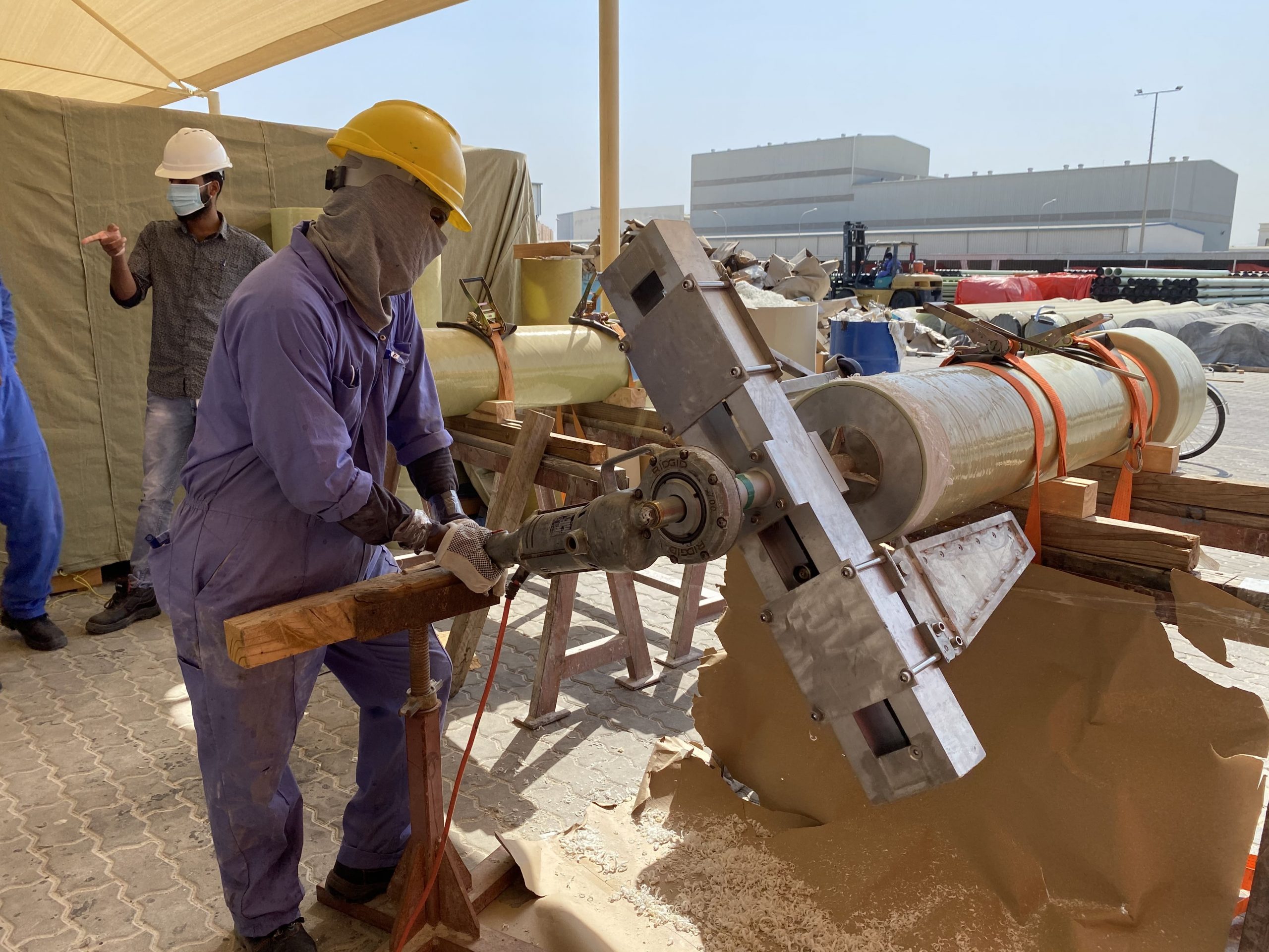
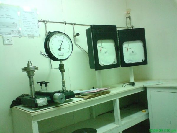
IN HOUSE TESTING & INSPECTION
To enable distribution and manufacturing oriented businesses, CPI Quality Control module will help you automate the quality control processes and tests for serialized, lot or batch tracked inventory items as well as for non-inventory items such as environmental or laboratory metrics. CPI QA/QC is fully equipped with all the resources required to comply with International Standards and Customer Requirements. CPI is accredited by TUV Nord for ISO 9001 & ISO 14001 Certification for quality management and environmental systems. Also successfully undergone audits and product testing and acquired product approval from FM 1614, NSF/ANSI 61, API 15 HR and API 15 LR. CPI obtained various customer approvals through stringent audits and product qualifications, testing and complete compliance to the customer specification. Listed as approved vendor from major clients such as PDO, BP, Saudi Aramco, KNPC, KOC, EIL and ONGC.
Materials received by CPI shall be subjected to the incoming inspection as per the approved inspection & test plans and procedures as applicable which include raw material, Ancillaries and customer properties
All the in process checks are carried out as per customer approved manufacturing and inspection Test plans and procedures for each stage of manufacturing. All work is being performed by qualified Forman’s and supervised 100% by trained and well experienced supervisors. Additionally being monitored by the dedicated process controllers.
The shop process real time data is being recorded in the birth certificate for each item being produced are the medium for setting up manufacturing operations in consecutive sequence and for establishing the points of inspection within a group of operations. With the process sheet, the drawings, specifications an applicable SOP’s, the QC process controller will inspect the work at various pre-determined points of manufacture. Suitable corrective and preventive action being ensured as the outcome of failure analysis if any. Upon completion of item, being inspected with a frequency of 100 % product sampling for visual and dimensional checks. Critical dimensions, mechanical properties, STHP test, LOI test and Tg tests are being performed lot wise as per the required specification and applicable ITP.
Each CPI process for receipting an item, such as a Purchase Order or Factory Order receipt can be set to a user defined status, eg. Quarantined or QC in Progress, and are assigned their defined tests and test specifications as per the customer approved inspection and Test plans. This saves time and effort. As test are performed, results from each test specification is being recorded along with who tested, the date and unlimited notes required to elaborate on the test procedure or results added.
Hydrostatic Testing Requirements & Procedures
1. Test Preparation
- All supports, guides, and anchors must be in place prior to pressure testing. All pipe sections shall be adequately supported and restrained before the start of Hydro testing.
- The pipeline shall be completely backfilled prior to the hydrotest except for the test-ends, tie-in connections and joints. These exposed sections shall be kept as short as possible.
- All valves must be independently supported prior testing.
- All joints shall be fully cured completed in accordance with manufacturer’s specifications before pressure testing.
- Before carrying out any pressure test, the area of the test shall be tapped with warning tape and warning signs erected at all access points.
- Water sources and disposal shall be discussed and approved from the principal/ facility owner.
- Filling the test section shall be done by pigging.
- Pipe soil temperature shall be measured and recorded at each end and one at the mid length of pipeline using thermocouple type instrument with digital read out and print out.
- Temporary test header shall be hydrostatically tested 1.25 times of testing pressure before connect to pipelines.
- Temporary pig launchers and receivers shall be approved by the Company prior to use and shall be flanged if a permanent flange is available
- All the GRE joints should be left exposed.
- Road / wadi crossings shall be tested separately before the installation.
2. Flushing
On completion of installation, GRE piping systems should be flushed in order to avoid any debris to damage or block portion of the network during the hydraulic pressure testing or service.
The medium used for flushing shall be soft pig, seawater or freshwater. Flushing is most effective when carried out from the highest entry point in the network. Flushing should be continued until effluent from the low point drains runs clear.
If compressed air is to be used as the driving medium for the pig , the air should be oil-free and the inlet line of the driving medium should be fitted with a pressure relief valve set at 7 bar (g).
All necessary precautions shall be taken to ensure that debris is not flushed into associated equipment or dead ends.
Flushing of pipe systems into tanks and/or vessels is not permitted unless approved by principal. The main headers, in general, shall be flushed out first and then all branches which connect to any equipment.
All instrument, vent and drains connections shall also be inspected for debris. The flushing and debris checking shall continue until all debris has been removed.
The main headers shall be flushed for 30 minutes and branches for 15 minutes or until clear water is seen, whichever is the longer. Alternatively, temporary strainers can be installed on discharge outlets in order to determine when the debris has been removed. When there is no further build-up evident on the strainer mesh, flushing can cease.
On completion of flushing and debris checking, all flanged connections shall be made up, with new gaskets to suit the relevant line specifications.
All GRE piping systems shall be hydraulic pressure tested after installation.
Systems, which are open to atmosphere, shall at least be subjected to a hydrostatic leak test, and may require full hydrostatic pressure, test if they could be subject to system pressure.
The following test stages shall be carried out:
3. Water Filling
Water shall be admitted at a suitable point in the piping or pipeline system and provision shall be made for bleeding the air at high(er) points (e.g. loosening of flange connection).
Any compressed air in the system may give erroneous results and all necessary measures shall be taken to remove air during filling.
For pipelines, this includes control of back-pressure, a steady, controlled filling rate, the use of a break tank and of at least two foam pigs with water in front and in between. If possible, the line should be filled from the lower end. Venting shall be carried out repeatedly at points in the test section where air might accumulate, e.g. at ancillary piping. The filling pig speed shall be controlled at approximately 0.6 m/s and should not exceed 1.8 m/s.
4. Temperature Stabilization
The temperature of the line-fill water should be stable before testing commences, prior to commencing the hydrostatic test, the water temperature should be within 1.0 °C of ground or seabed temperature. This shall be determined as the difference between average pipe temperature and average ground temperature over the test section length.
Pressure and temperatures, including ambient, shall be recorded every hour during the stabilisation period.
The test section temperature and the ambient temperature (ground/air/water) shall be plotted against time during the temperature stabilisation period. Air Content Determination
The air content of the filled line shall be determined during initial pressurization.
Percentage air content = (Volume of air / Volume of line) 100
If the air content exceeds 0.2% of the line volume, testing shall be terminated and an
Investigation shall be carried out to determine the cause. The test section should be emptied and refilled at the discretion of the Company.
5. Hydrostatic Strength Test
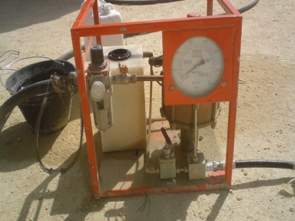
The “Strength test” shall be carried out at rate of 2 bar per minute till the required pressure, value of which is achieved with 1.5 times the Design Pressure or 0.89 times the qualified pressure, whichever is lower and held for a period of 1 hour. After the test the line has to be inspected to see indication of any leakage or damage occurred during test.
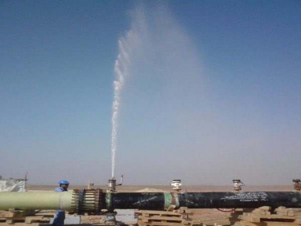
6. Hydrostatic Leak-Tightness Test
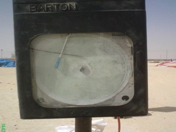
During both tests, the pressure and temperature shall be recorded continuously. Pressure and temperature recorder shall be used.
In the event of a pressure drop during the leak-tightness test, a “step-test” shall be performed. In this test, due to several parameters like the temperature variation, the pressure has to be controlled and monitored. In this test, the test section shall be re-pressurised to the leak-tightness test pressure (i.e. 1.1 times design pressure) and after each hour the pressure shall be recorded and the section re-pressurised by adding water. The quantity of water required to bring the section back up to test pressure shall also be recorded. If the quantity of water added each hour shows a decreasing trend, then it may be considered that the pipeline is tight. If the quantity of water added remains constant, then it can be assumed that the pipeline is not leak-tight.
This can be considered as an additional check to determine whether any pressure variation has been caused due to temperature changes can eliminate the doubt of piping system leakage.
GRE installation contractor shall provide a list of the testing equipment he is intending to use along with the testing procedure.
Water shall be admitted at a low point in the system and provision shall be made for bleeding the air at high points. Any air pockets may give erroneous result as well as damage the piping during the pressure test.
Venting shall be carried out repeatedly at points in the test section where air might accumulate, e.g. at ancillary piping.
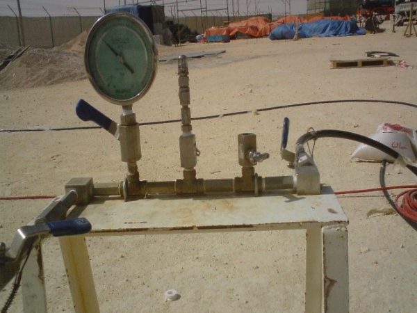
Therefore, the line must be equipped with flanged head with valve and manometer for filling at lower point, and flanged head with bleed valve at upper point.
It is advised to contractor to use a pressure safety valve adjusted at 3% above specified test pressure.
Over-torque of flanges to stop leaks during the filling stage is not permitted. Leaking flanges shall be remade with new gaskets and re-tested. If leakage still occurs, flanges must be replaced.
Insertion of “Manual Piping Shutter” between Composite Flanges shall not be used. Hydraulic test has to be done from fixed metallic closing device to fixed metallic closing device.
7. Depressurization
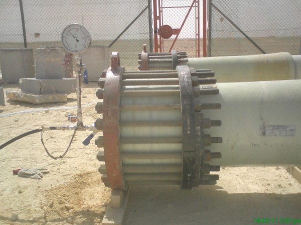
8. Flanged Spool Hydrotesting
Flanged spools, spools that have flanged ends and can be blinded independently using steel blind flanges, pressure heads or the Hydrotesting launcher and receiver, shall be hydrotested separately if the hydrotest of the entire pipeline is not required.
Hydrotest procedure also valid for spools hydrotest regardless the arrangement and size.