Composite Pipes Industry with its Engineering department capability and experience can provide customize Engineering solution to customer starting at the early stage of the project.
CPI has a big advantage of having in-house design capability along with manufacturing unit of GRP piping System. Production difficulties encountered along with effective quality system provides necessary input to design so as to take into account and make necessary changes to the GRP product design to provide economical and reliable product which meet the customer requirement up to highest level of customer satisfaction.
CPI Engineering department are fully equipped for designing the GRP pipes and fittings system suit for Underground and Above ground application as per ISO 14692, AWWA M45,AWWA 950 API 15 LR & HR, Shell or any other customer specified standard and specification. U/G pipe design calculations covers live and dead loads effects on the pipe in addition to the effect of internal pressure and vacuum pressure on the adequacy of pipe for buckling, combined strain and allowable stress as per AWWA M-45 and C-950.
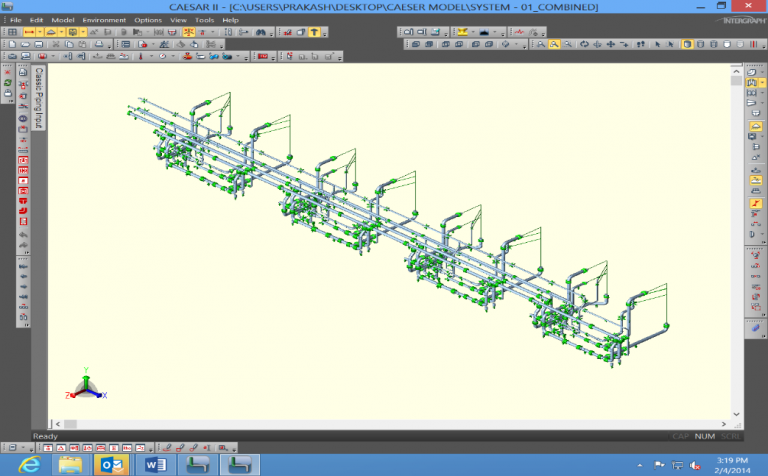
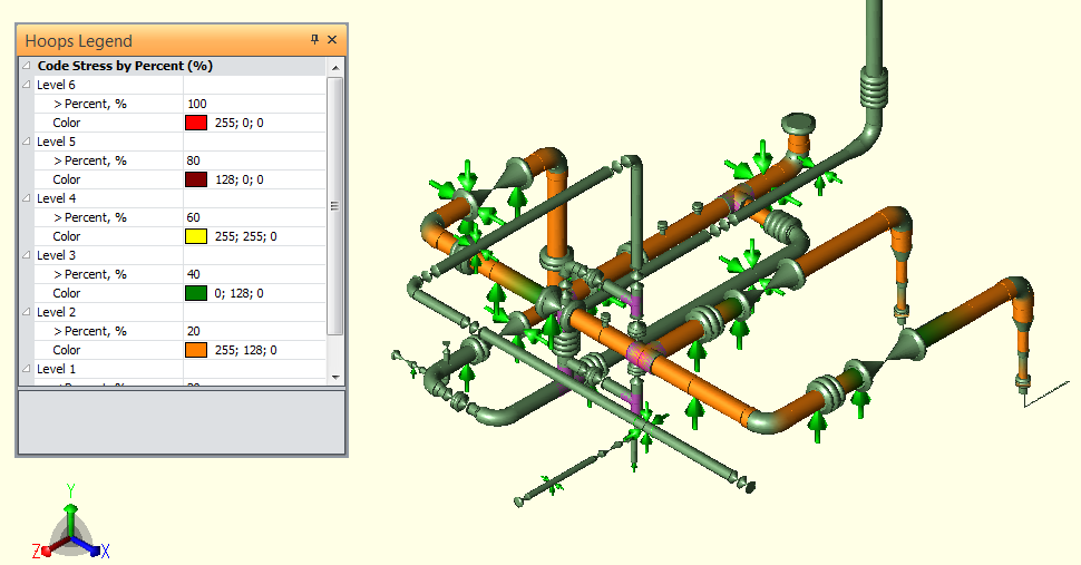
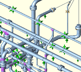
Complete Stress Analysis of piping system will be done using Caesar II which include the metallic pipes and equipment for system design. The results of analysis will provide to customer with all required details, recommendations and modification in the system if required. CPI’s rich experience in this field will help to providing the customer with the most economical and cost effective design of the piping and pipeline system taking in to consideration all related project parameter. This analysis will also lead to use of proper process and design detail during manufacturing and installation. Doing such analysis is very essential for success of any project. CPI is not only limited to the static stress analysis, it can be extended to dynamic stress analysis (water hammer calculation and model analysis) and equipment analysis (static and rotating equipment) which involve allowable nozzle load as per international standard. CPI can provide water hammer or surge analysis to find out the effect of sudden activation and deactivation of valves.
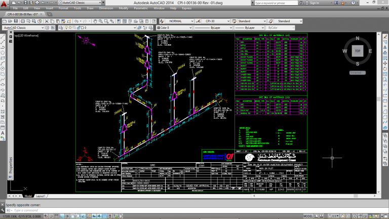
CPI is Equipped with latest version of PIPENET Software which is used for pipe sizing design , head loss calculation and water hammer calculation. Based on client input (i.e. General Arrangement Drawing / Alignment sheet) CPI provide the custom made isometric drawing. CPI also provide the Stress Isometric with support markup and Bill of material. Isometric with support markup drawing is used at any stage during or after project execution. This will result in cost savings for all parties involved and eliminate any changes of miscommunication and lack of detail.
Engineering Services:
- Design of GRP Pipes and Fittings :
- Flexibility Analysis :
- Surge Analysis :
- Engineering Drawing :
- Isometric Drawing :
- Design of Pipe support, anchors, guide and thrust block :
- Detail Fabrication drawing and shop Spool drawing :
- Preparation of Bill of Material :
- Preparation of Bill of Material :
CPI provides below other engineering calculation in order to give the full solution of GRE product and meet the customer requirement and satisfaction.
- Design and failure envelope of GRE pipes and fittings
- Technical Data sheet
- Buoyancy calculation
- Elastic Bending Radius Calculation
- Adhesive joint Calculation
- Water Hammer Calculation
- Hydro test Calculation
- Preparation of Technical Quotation :
System Design
General
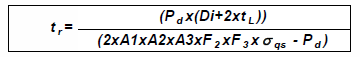
The aim of system design for GRP piping systems is to ensure that they shall perform satisfactorily and sustain all stresses and deformations during construction/installation and throughout their service life. This clause identifies the service design criteria and the loads to which GRP may be subjected. In order to provide sufficient robustness during handling and installation, min. reinforced wall thickness of any GRP pipe component shall not be less than 3mm. Minimum Reinforced wall thickness of pipe is calculated based on hoop stress and by considering ISO 14692 as below-
Design Envelope
With Isotropic materials (properties of a material are identical in all direction) such as steel, the effect of combined stresses (pressure and non-pressure induced) are greatly simplified as hoop and axial strength are identical. This results give a significant margin in allowable strength to accommodate this extra axial stress as the pressure induced. Axial stress (load) is exactly one half of hoop stress. Whereas, for anisotropic material (properties of a material are different in all direction) such as filament wound GRP pipes, hoop and axial strength are significantly different. Axial stress is not exactly half of hoop stress. Therefore hoop strength is significantly greater than the axial strength.
If the effective hoop and axial stresses, σheff, and σaeff, lie inside the factored long-term design envelope, then the GRP pipes and fittings designed within the acceptable limits. If the stresses lie outside this envelope, then high-rated GRP pipes and fittings, i.e. a thicker walled pipes and fittings shall be chosen and repeat the same stress calculation until it lies within the acceptable limits of factored long-term design envelope.
Thrust Block Design
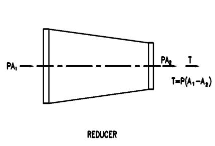
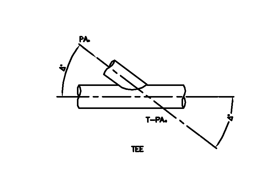
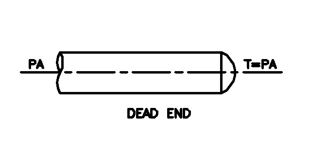
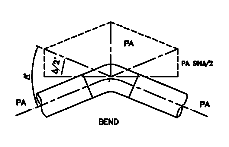
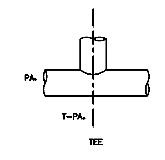
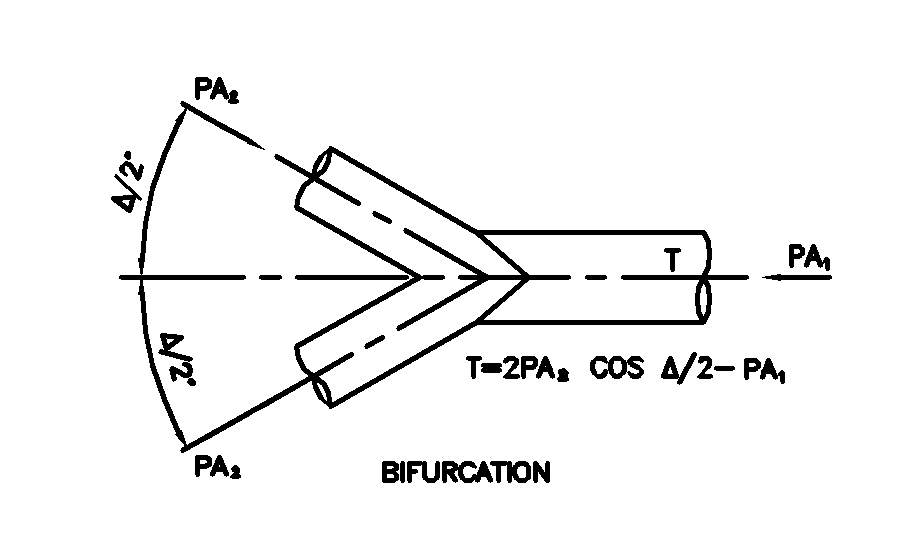
Unbalanced thrust forces occur in pressure pipelines at changes in direction (i.e., elbows, wyes, tees, etc.), at changes in cross-sectional area (i.e., reducers), or at pipeline terminations (i.e., bulkheads). These forces, if not adequately restrained, may cause pipeline movement resulting in separated joints and/or pipe damage.
Thrust forces are:
- hydrostatic thrust due to internal pressure of the pipeline and
- hydro-dynamic thrust due to changing momentum of flowing fluid.
Since most pressure lines operate at relatively low velocities, the hydrodynamic force is very small and is usually ignored.
Typical examples of hydrostatic thrust are shown in below Figure. The thrust in dead ends, tees, laterals, and reducers is a function of internal pressure P and cross-sectional area A at the pipe joint.
Thrust Force Definitions
Thrust Block
Support Design
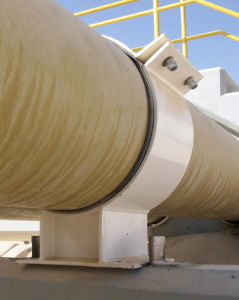
The following requirements and recommendations apply to the use of system supports.
- Supports shall be spaced to avoid sag (excessive displacement over time) and/or excessive vibration for the design life of the piping system.
- In all cases, support design should be in accordance with the CPI guidelines .CPI will provide the support design for above ground pipe system.
- Valves or other heavy attached equipment shall be independently supported.
- GRP piping should be adequately supported to ensure that the attachment of hoses at locations such as utility or loading stations does not result in the pipe being pulled in a manner that could overstress material.